This is an update to my original blog post
This article will demonstrate how to use the Output Sequencer feature of 14Point7 wideband controllers to maximize accuracy between the wideband controller and your Megasquirt ECU when using the analog interface. If you are using Spartan 3 and interfacing to Megasquirt via digital CAN Bus then the you do not need the Output Sequencer feature.
This article is applicable to most 14Point7 Wideband controllers including, Spartan 2, Spartan 2 OEM, Spartan 3 Lite, and Spartan 3 if you are not using CAN Bus.
Theory of Operation
When a wideband controller is first powered on, it takes about 30 seconds to a minute for the oxygen sensor to heat up to a normal operating temperature of 780 degrees Celsius. During the warmup time there is no valid AFR readings and the Output Sequencer makes use of this “dead time” to output two calibration voltages.
When 14Point7 wideband controllers are first powered on, for the first 5 seconds it will output 1.66 volts on the analog linear output, the next 5 seconds will output 3.33 volts. If there are no errors then 1.66 volts will be read as 13.33 AFR by Megasquirt and 3.33 volts will be read as 16.66 AFR.
There are 3 common types of errors in electronic systems, offset errors, linear errors, and non-linear errors. Non-linear errors are typically very small and are hard to compensate for, so the Output Sequencer does not compensate for non-linear errors. The Output Sequencer only compensates for offset and linear errors.
An example of offset error would be ground offsets caused by high currents flowing through ground or poor grounding between the wideband controller and your Megasquirt ECU. It does not matter the actual source of the offset error because we will calibrate for the aggregate of all offset errors.
An example of linear error would be errors caused by voltage regulators, it could be the 5 volt regulator on the wideband is not perfectly outputting 5 volts or the 5 volt regulator on your Megasquirt ECU is not perfectly outputting 5 volts. Like with offset errors it does not matter the actual source of the linear error because we will calibrate for the aggregate (product) of all linear errors.
We have 2 unknown errors, Offset and Linear. We also have 2 calibration voltages which we use to construct two equations. By using simple algebra, we can solve for both errors and then we encode the compensation for both errors into a “Custom Linear WB” curve and enter that into Tuner Studio.
Calibration Process Overview
The process to compensate for offset and linear errors is a 2-step process. The first step is to physically install the wideband controller and using the default “Custom Linear WB" settings in Tuner Studio. The 2nd step is to use the Output Sequencer voltages read by your MegaSquirt as shown by Tuner Studio to calculate a new “Custom Linear WB" setting, entering the new settings into Tuner Studio and writing the new settings to your MegaSquirt.
Step 1 of Calibration:
Install and wire up your wideband controller according to the user manual. Please make sure to ground the Electronics Ground where your Megasquirt ECU is grounded and ground the Heater Ground to the chassis, this will minimize offset errors.
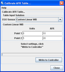
In Tuner Studio, tools->Calibrate AFR Table->EGO Sensor select "Custom Linear WB", enter the values shown in the picture below and write changes to Megasquirt.

Step 2 of Calibration:
While Tuner Studio is connected to you Megasquirt ECU and is actively displaying AFR data, cycle power to the wideband controller and write down the 2 AFRs shown by Tuner Studio during the first 5 seconds and then during the next 5-10 seconds. For this example lets use 13 AFR and 17.1 AFR.
Download and open the Microsoft Excel worksheet here

Assuming that the first 5 seconds AFR shown by Tuner Studio is 13 AFR and the 5-10 seconds AFR shown by tuner studio is 17.1 AFR, you would enter 13 and 17.1 into the orange colored cells in the Excel worksheet, of course instead of 13 AFR and 17.1 AFR you would enter the AFRs shown by your Tuner Studio. Once those two AFRs are entered, the numbers in the green box will generate a new “Custom Linear WB" setting that compensates for offset and linear errors.
In Tuner Studio, tools->Calibrate AFR Table->EGO Sensor select "Custom Linear WB", enter the values shown in green cells from the Excel worksheet and write the changes to your Megasquirt. In my example, the first 5 seconds AFR is 13 AFR and the 5-10 AFR is 17.1 AFR, my calculated new “Custom Linear WB" settings are 10.89 AFR @ 0 volts and 19.02 AFR @ 5 volts.

Now if everything was done correctly then your Megasquirt ECU will now be able to read AFRs with 1/10th AFR accuracy. Cycle power to Spartan 2 again and now the first 5 seconds AFR should be 13.3 +/- 0.1 AFR and the 5-10 seconds AFR should be 16.7 AFR +/- 0.1 AFR. Because Megasquirt uses only upto the first decimal place to represent AFR, the best you can do is +/- 0.1 AFR accuracy.


